

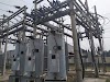
Transformer
The
assembly of the apparatus to change some characteristics of the electric power supply is
called substation. The present-day electrical power system is A.C. i.e.
electrical power is generated, transmitted, and distributed in the form of the
alternating current. The electric power is produced at power plant stations
which are located at favorable places generally quite away from the consumers.
It is delivered to the consumers through a large network of transmission and
distribution.
A transformer is a device that transfers electric current from one circuit to another, usually by the principle of mutual induction. During this process, the frequency remains constant whereas the voltage can be increased or decreased according to the need. This transfer of electricity occurs with the help of two coils. One of which is known as the Primary Coil, which is connected to a source of alternating current. The other is known as the Secondary Coil, and it is connected to an external circuit.
Substations
maybe owned and operated by an electrical utility, or may be owned by a large
industrial or commercial customers.
1.1 Classification of Substation
Ø
Step-Up Substation
Ø
Step-Down Substation
Ø
Primary Grid Substation
Ø
Secondary Grid Substation
Ø Distribution Substation
 |
| Fig1.1: Transformer |
1.2 Transformer Substation
They
are known as transformer substations because the transformer is the main
component employed to change the voltage level, depending upon the purposed
served transformer substations. A transmission
substation connects two or more transmission lines. The simplest case is
where all transmission lines have the same voltage. In such cases, substation
contains high-voltage switches that allow lines to be connected or isolated for
fault clearance or maintenance of transformer. A transmission station may
have transformers to convert between two transmission
voltages, voltage control/power factor correction devices such as
capacitors, reactors.
1.3 Step-Up Substation
The
generation voltage is stepped up to high voltage to affect the economy in the transmission of electric power. These are generally located in the powerhouses
and are of the outdoor type. Such types of substations generate low
voltage like 3.3, 6.6, 11, or 33kV. This voltage is stepped up by the help of a
step-up transformer for transmitting the power over large distances. It is
located near the generating substation.
1.4 Step-Down Substation
This the substation is placed near the load Centre where the primary distribution is
stepped down for sub-transmission. The secondary distribution transformer feeds
the consumer through the service line.
1.5 Primary Grid Substation
This
substation lowered the value of primary stepped-up voltages. The output of the
primary grid substation acts as the input of the secondary substations. The
secondary substation is used for stepping down the input voltage to more
lowered for further transmission.
1.6 Secondary Grid Substation
At
a secondary substation, the voltage is further stepped down to 11KV. The 11KV
lines run along the important road of the city. The secondary substations are
also of the outdoor type.
1.7 Distribution Substation
A
distribution substation transfers power from the transmission system to the
distribution system of an area. The input for a distribution substation is
typically at least two transmission or sub-transmission lines. Distribution
voltages are typically medium voltage, between 2.4 and 33 kV depending on the
size of the area served and the practices of the local utility. Besides
changing the voltage, the job of the distribution substation is to isolate
faults in either the transmission or distribution systems. Distribution
substations may also be the points of voltage regulation, although on long
distribution circuits (several km/miles).
 |
| Distribution system |
1.8 Working principle of Transformer
Transformer works on the principle of Faraday’s Law of Mutual Induction. This principle states that the rate of change of flux is directly proportional to the induced electromagnetic flux.
Similarly, in a transformer, when an alternating current flow through one of the coils, it creates a magnetic field around it, which constantly produces a changing magnetic flux and so, when another coil is brought near it, some of the EMF is also induced in the secondary coil as well. Since the secondary coil forms a closed loop, the EMF produces the current in it as well. These windings are usually made on an iron core to make the magnetic field stronger, and laminated afterward so that the flux does not weaken due to air, which is a perfect insulator. But still, some power losses are observed such as Eddy Current losses and Hysteresis loss.
 |
| Fig 1.2: Working Principle of Transformer |
1.9 Power Transformer
The power transformer is an electric device that is used to step up or step down the voltage level of the supply fed to its primary winding. The stepping up or down depends upon the number of turns of the primary and secondary winding. If the number of turns on both the windings is the same, and the losses of the transformer are negligible, we may conclude that the voltage across each of the windings is the same. In this case, the transformer is just utilized in isolating two electrical circuits.
Generally, the power transformer is used in stepping up the voltage of the supply in order to decrease the transmission losses and then stepping down is done for the distribution purpose at the load centers.
|
|
Item |
Rating |
Item |
Rating |
|||
|
Company Name |
TOSHIBA |
OPTG. Pressure of PRV |
10 PSI |
|||
|
Transformer Type |
OUTDOOR |
Standard |
ANSI C57.12.10&C57.12.90 |
|||
|
Type of Cooling |
ONAN/ONAF |
Frequency |
|
HZ |
50 |
|
|
Rated MVA |
5/6.25 |
Insulation Level |
HV |
kV |
LI 200 AC 70 |
|
|
Rated kV |
HV |
33 |
LV |
LI 110 AC 34 |
||
|
LV |
11.55 |
LVN |
LI 110 AC 34 |
|||
|
Rated Line Current (Amps.) |
HV |
87.5/109.3 |
Core & Coil |
KG |
6800 |
|
|
LV |
249.9/312.4 |
Tanks & Fittings |
3600 |
|||
|
Vector Group |
Dyn 1 |
Mass Of Oil |
3400 |
|||
|
Number of Phases |
3 |
Total Mass |
13800 |
|||
|
% Impedance HV/LV |
6 |
Transport Mass |
10800 |
|||
|
Temp rise ˚C |
Top Oil |
60 |
Volume of Oil |
L |
3542 |
|
|
AVG WDG |
65 |
Tank Strength |
+10 PSI-8 PSI |
|||
|
Year of MFG. |
Sep-11 |
Maker's Reference No |
|
|||
|
Diagram DRG No. |
P6.25M-104 |
Polarity |
SUBTRACTIVE |
|||
|
Maker's Serial No |
157 |
|
||||
|
Item |
Rating |
Item |
Rating |
||
|
Company Name |
TOSHIBA |
Consumer LOI. No. |
830/EVL/2003 |
||
|
KVA |
3333/4166 |
Type of Cooling |
OA/FA |
||
|
Volts at No Load |
H.V. |
33000 |
Frequency |
HZ |
50 |
|
L.V. |
11550/1.732 |
Impedance Voltage % |
5.87 |
||
|
Amperes |
H.V. |
101/126.3 |
Polarity |
SUBTRACTIVE |
|
|
L.V. |
500/625 |
Total Weight |
KG |
7300 |
|
|
Phase |
H.V. |
1 |
Weight of Coil |
1380 |
|
|
L.V. |
1 |
Type of Oil |
MINERAL OIL |
||
|
Out Line DRG. No. |
3 OG 7952 |
Conductor Material |
H. V |
COPPER |
|
|
Serial No. |
624603 |
L. V. |
COPPER |
||
|
OP. Pressure |
+10, -8 PSI |
Year of MFG |
2003 |
||
|
H. V. BIL |
200 kV |
Temp. Rise Oil/ Winding Above Ambient Air Temp. of |
˚C |
60/65 |
|
|
L. V. BIL |
110 kV |
40 |
|||
1.10 Step up and Step-down Transformer
The step-up transformer transforms a low voltage, high current AC into a high voltage, low current AC system. In this type of transformer, the number of terns in the secondary winding is greater than the number of turns in the primary side winding which as shown in figure 4.10(a).
 |
| Fig 1.4: Step up (a) and Step-Down (b) TransformerAdd caption |
Instrument transformer is a special transformer that is used in the electrical power system for stepping down currents and voltages of the system for measuring and protection purposes. The primary winding of the transformer is connected to the high voltage or high current circuit, and the meter or relay is connected to the secondary circuit. Instrument transformers may also be used as an isolation transformer so that secondary quantities may be used in phase-shifting without affecting another primary connected device.
 |
| Fig 1.4: Instrument TransformerAdd caption |
The potential transformer may be defined as an instrument transformer used for the transformation of voltage from a higher value to the lower value. This transformer step down the voltage to a safe limit value which can be easily measured by the ordinary low voltage instrument like a voltmeter, wattmeter and watt-hour meters, etc.


0 Comments